Home » Posts filed under DIY
Showing posts with label DIY. Show all posts
This is not officially published by PCB producer, and I don't have any promotional relationship with PCB seller which is KPRepublic. I write this to make as a note for me and for fellow hobbyists out there if they are stuck with programming steps on XD60 rev3 PCB.
It was a long time ago since I was posted on my blog, been busy with work and hobby lately. I don't know how I can get into this hobby, but I just read it somewhere and see some cool keyboards out there with some customization and nice keycaps to make a "thock" sound which is really relaxing and I decided to find out about it. Here I am now with my first custom board XD60 rev3 and supported many layouts like arrow cluster on 60% keyboards.
So the first question appear on my head was how to flash this little beast? This PCB supported by QMK firmware and that firmware so powerful with many functions could be added into the keyboards. First of all, go to docs.qmk.fm
You should see there is instruction on there to build the QMK environment.
From msys2 website you have to choose the installer based on your PC architecture.
You can read from there for a better explanation to install the application. After all installation process succeeded, you can open the MSYS2 MinGW 64-bit application and it should look like this.
Run the application and Navigate to your QMK repository. For example, if it's in the root of your c drive: "cd /c/qmk_firmware"
It's pretty self-explanation from QMK website. Next step was Run "util/qmk_install.sh" from the command line and follow the prompts. All command should be run without quotes.
If all of this step was already done, you would be ready to compile your keymap on the keyboard. I assume if you are Windows user you could find qmk_firmware files in C:\msys64\home\(your windows username)\qmk_firmware
The first you need to do is select keyboards folder and chooses xd60 folder.
Select it and then you could see three folders there and select keymaps folder. Make a new folder with your name or whatever as you wish the folder's name. As an example, I make folder rudi since it is my name.
Now copy keymap.c on default keymaps folder and paste it into rudi folder. You can change the keymaps later. This step just to make sure QMK build environment work as expected.
Type "make xd60/rev3:rudi" on your MSYS2 application like this. Make sure which version your board it is, if it is rev2 change it accordingly.
If all OK sign has appeared, you can find hex files already made in your qmk_firmware folder. Find file with "xd60_rev3_rudi.hex" name. Now you are ready to flash the keyboard. Make a change to keymaps as your wish on rudi keymaps folder which we make before and compile it again if you are not satisfied with keymaps layout.
After we have gone so far, now we need to download the latest release QMK toolbox. After the download finished, open it and select your hex files was made before.
I blurred my Windows username just for privacy. Tick Auto-Flash and connect your PCB to your computer and press the button on the back of the PCB. It should be connected and if not try to install driver zadig.exe
If everything was done correctly it would auto flash the moment you press the button from the back of the PCB. From the above picture, you could see it is already flashed and your XD60 ready to type on! Enjoy your DIY keyboard from now!
So the first question appear on my head was how to flash this little beast? This PCB supported by QMK firmware and that firmware so powerful with many functions could be added into the keyboards. First of all, go to docs.qmk.fm
You should see there is instruction on there to build the QMK environment.
You can read from there for a better explanation to install the application. After all installation process succeeded, you can open the MSYS2 MinGW 64-bit application and it should look like this.
Run the application and Navigate to your QMK repository. For example, if it's in the root of your c drive: "cd /c/qmk_firmware"
It's pretty self-explanation from QMK website. Next step was Run "util/qmk_install.sh" from the command line and follow the prompts. All command should be run without quotes.
If all of this step was already done, you would be ready to compile your keymap on the keyboard. I assume if you are Windows user you could find qmk_firmware files in C:\msys64\home\(your windows username)\qmk_firmware
The first you need to do is select keyboards folder and chooses xd60 folder.
Select it and then you could see three folders there and select keymaps folder. Make a new folder with your name or whatever as you wish the folder's name. As an example, I make folder rudi since it is my name.
Now copy keymap.c on default keymaps folder and paste it into rudi folder. You can change the keymaps later. This step just to make sure QMK build environment work as expected.
Type "make xd60/rev3:rudi" on your MSYS2 application like this. Make sure which version your board it is, if it is rev2 change it accordingly.
If all OK sign has appeared, you can find hex files already made in your qmk_firmware folder. Find file with "xd60_rev3_rudi.hex" name. Now you are ready to flash the keyboard. Make a change to keymaps as your wish on rudi keymaps folder which we make before and compile it again if you are not satisfied with keymaps layout.
After we have gone so far, now we need to download the latest release QMK toolbox. After the download finished, open it and select your hex files was made before.
I blurred my Windows username just for privacy. Tick Auto-Flash and connect your PCB to your computer and press the button on the back of the PCB. It should be connected and if not try to install driver zadig.exe
If everything was done correctly it would auto flash the moment you press the button from the back of the PCB. From the above picture, you could see it is already flashed and your XD60 ready to type on! Enjoy your DIY keyboard from now!
This is not officially published by PCB producer, and I don't have any promotional relationship with PCB seller which is KPRepublic. I write this to make as a note for me and for fellow hobbyists out there if they are stuck with programming steps on XD60 rev3 PCB.
It was a long time ago since I was posted on my blog, been busy with work and hobby lately. I don't know how I can get into this hobby, but I just read it somewhere and see some cool keyboards out there with some customization and nice keycaps to make a "thock" sound which is really relaxing and I decided to find out about it. Here I am now with my first custom board XD60 rev3 and supported many layouts like arrow cluster on 60% keyboards.
So the first question appear on my head was how to flash this little beast? This PCB supported by QMK firmware and that firmware so powerful with many functions could be added into the keyboards. First of all, go to docs.qmk.fm
You should see there is instruction on there to build the QMK environment.
From msys2 website you have to choose the installer based on your PC architecture.
You can read from there for a better explanation to install the application. After all installation process succeeded, you can open the MSYS2 MinGW 64-bit application and it should look like this.
Run the application and Navigate to your QMK repository. For example, if it's in the root of your c drive: "cd /c/qmk_firmware"
It's pretty self-explanation from QMK website. Next step was Run "util/qmk_install.sh" from the command line and follow the prompts. All command should be run without quotes.
If all of this step was already done, you would be ready to compile your keymap on the keyboard. I assume if you are Windows user you could find qmk_firmware files in C:\msys64\home\(your windows username)\qmk_firmware
The first you need to do is select keyboards folder and chooses xd60 folder.
Select it and then you could see three folders there and select keymaps folder. Make a new folder with your name or whatever as you wish the folder's name. As an example, I make folder rudi since it is my name.
Now copy keymap.c on default keymaps folder and paste it into rudi folder. You can change the keymaps later. This step just to make sure QMK build environment work as expected.
Type "make xd60/rev3:rudi" on your MSYS2 application like this. Make sure which version your board it is, if it is rev2 change it accordingly.
If all OK sign has appeared, you can find hex files already made in your qmk_firmware folder. Find file with "xd60_rev3_rudi.hex" name. Now you are ready to flash the keyboard. Make a change to keymaps as your wish on rudi keymaps folder which we make before and compile it again if you are not satisfied with keymaps layout.
After we have gone so far, now we need to download the latest release QMK toolbox. After the download finished, open it and select your hex files was made before.
I blurred my Windows username just for privacy. Tick Auto-Flash and connect your PCB to your computer and press the button on the back of the PCB. It should be connected and if not try to install driver zadig.exe
If everything was done correctly it would auto flash the moment you press the button from the back of the PCB. From the above picture, you could see it is already flashed and your XD60 ready to type on! Enjoy your DIY keyboard from now!
So the first question appear on my head was how to flash this little beast? This PCB supported by QMK firmware and that firmware so powerful with many functions could be added into the keyboards. First of all, go to docs.qmk.fm
You should see there is instruction on there to build the QMK environment.
You can read from there for a better explanation to install the application. After all installation process succeeded, you can open the MSYS2 MinGW 64-bit application and it should look like this.
Run the application and Navigate to your QMK repository. For example, if it's in the root of your c drive: "cd /c/qmk_firmware"
It's pretty self-explanation from QMK website. Next step was Run "util/qmk_install.sh" from the command line and follow the prompts. All command should be run without quotes.
If all of this step was already done, you would be ready to compile your keymap on the keyboard. I assume if you are Windows user you could find qmk_firmware files in C:\msys64\home\(your windows username)\qmk_firmware
The first you need to do is select keyboards folder and chooses xd60 folder.
Select it and then you could see three folders there and select keymaps folder. Make a new folder with your name or whatever as you wish the folder's name. As an example, I make folder rudi since it is my name.
Now copy keymap.c on default keymaps folder and paste it into rudi folder. You can change the keymaps later. This step just to make sure QMK build environment work as expected.
Type "make xd60/rev3:rudi" on your MSYS2 application like this. Make sure which version your board it is, if it is rev2 change it accordingly.
If all OK sign has appeared, you can find hex files already made in your qmk_firmware folder. Find file with "xd60_rev3_rudi.hex" name. Now you are ready to flash the keyboard. Make a change to keymaps as your wish on rudi keymaps folder which we make before and compile it again if you are not satisfied with keymaps layout.
After we have gone so far, now we need to download the latest release QMK toolbox. After the download finished, open it and select your hex files was made before.
I blurred my Windows username just for privacy. Tick Auto-Flash and connect your PCB to your computer and press the button on the back of the PCB. It should be connected and if not try to install driver zadig.exe
If everything was done correctly it would auto flash the moment you press the button from the back of the PCB. From the above picture, you could see it is already flashed and your XD60 ready to type on! Enjoy your DIY keyboard from now!
Here is LC Meter that you can build yourself, you can find the schematic, board design also included and description for building from Phil Rice VK3BHR
Another site sells this LC Meter and looks neat. It would help to identify the components easily especially for the radio amateur. Try to get it one.
" This is one of the most accurate and simplest LC inductance/capacitance Meters that one can find, yet one that you can easily build yourself. This LC Meter allows to measure incredibly small inductances starting from 10nH to 1000nH, 1uH to 1000uH, 1mH to 100mH and capacitance from 0.1pF up to 900nF. LC Meter's circuit uses an auto ranging system so that way you do not need to spend time selecting ranges manually. Another neat function is the reset switch that will reset the initial inductance/capacitance, making sure that the final readings of the LC Meter are as accurate as possible."
Link : http://electronics-diy.com/lc_meter.php
Another site sells this LC Meter and looks neat. It would help to identify the components easily especially for the radio amateur. Try to get it one.
" This is one of the most accurate and simplest LC inductance/capacitance Meters that one can find, yet one that you can easily build yourself. This LC Meter allows to measure incredibly small inductances starting from 10nH to 1000nH, 1uH to 1000uH, 1mH to 100mH and capacitance from 0.1pF up to 900nF. LC Meter's circuit uses an auto ranging system so that way you do not need to spend time selecting ranges manually. Another neat function is the reset switch that will reset the initial inductance/capacitance, making sure that the final readings of the LC Meter are as accurate as possible."
Link : http://electronics-diy.com/lc_meter.php
Here is LC Meter that you can build yourself, you can find the schematic, board design also included and description for building from Phil Rice VK3BHR
Another site sells this LC Meter and looks neat. It would help to identify the components easily especially for the radio amateur. Try to get it one.
" This is one of the most accurate and simplest LC inductance/capacitance Meters that one can find, yet one that you can easily build yourself. This LC Meter allows to measure incredibly small inductances starting from 10nH to 1000nH, 1uH to 1000uH, 1mH to 100mH and capacitance from 0.1pF up to 900nF. LC Meter's circuit uses an auto ranging system so that way you do not need to spend time selecting ranges manually. Another neat function is the reset switch that will reset the initial inductance/capacitance, making sure that the final readings of the LC Meter are as accurate as possible."
Link : http://electronics-diy.com/lc_meter.php
Another site sells this LC Meter and looks neat. It would help to identify the components easily especially for the radio amateur. Try to get it one.
" This is one of the most accurate and simplest LC inductance/capacitance Meters that one can find, yet one that you can easily build yourself. This LC Meter allows to measure incredibly small inductances starting from 10nH to 1000nH, 1uH to 1000uH, 1mH to 100mH and capacitance from 0.1pF up to 900nF. LC Meter's circuit uses an auto ranging system so that way you do not need to spend time selecting ranges manually. Another neat function is the reset switch that will reset the initial inductance/capacitance, making sure that the final readings of the LC Meter are as accurate as possible."
Link : http://electronics-diy.com/lc_meter.php
I made this add on for ESR Meter since I found something strange from my experiment. There is another way to test flyback or transformer which are still energized with bulb, but this add on still serve me well, so far so good.
By the way, you could test yoke too with this add on for your ESR Meter and don't forget about the note. Have a good day and still be careful when doing repair job. Thank you for coming here.
See this great idea that I created and kindly post by Mr Jestine Yong on his blog. You can test flyback and SMPS transformer under load with this.
Link : ESR Meter to detect magnetic field
By the way, you could test yoke too with this add on for your ESR Meter and don't forget about the note. Have a good day and still be careful when doing repair job. Thank you for coming here.
See this great idea that I created and kindly post by Mr Jestine Yong on his blog. You can test flyback and SMPS transformer under load with this.
Link : ESR Meter to detect magnetic field
I made this add on for ESR Meter since I found something strange from my experiment. There is another way to test flyback or transformer which are still energized with bulb, but this add on still serve me well, so far so good.
By the way, you could test yoke too with this add on for your ESR Meter and don't forget about the note. Have a good day and still be careful when doing repair job. Thank you for coming here.
See this great idea that I created and kindly post by Mr Jestine Yong on his blog. You can test flyback and SMPS transformer under load with this.
Link : ESR Meter to detect magnetic field
By the way, you could test yoke too with this add on for your ESR Meter and don't forget about the note. Have a good day and still be careful when doing repair job. Thank you for coming here.
See this great idea that I created and kindly post by Mr Jestine Yong on his blog. You can test flyback and SMPS transformer under load with this.
Link : ESR Meter to detect magnetic field
If you are a technician, don’t miss this Ring Tester on your repair bench. It is rare to find Linear Power Supply on our equipment today because everything was made with SMPS today. SMPS or Switch Mode Power Supply offers an efficiency and more light than Linear Power Supply with the same performance. It is hard to find a big bulky transformer today on our consumer electronic equipments today because everything were dominated by Switch Mode Power Supply.
The disadvantage about power supply which are difficult to troubleshoot because it’s complexity. We need a reliable tool to help us troubleshoot SMPS. You can’t depend on just one test equipment to repair SMPS, that is a hard job. I’ve found this tester really helped me to do a troubleshooting job. I would never do a repair job without this one because it helped me much.
I build this tester based on Blue Ring Tester schematic from Anatek Corporation manual. See below picture.
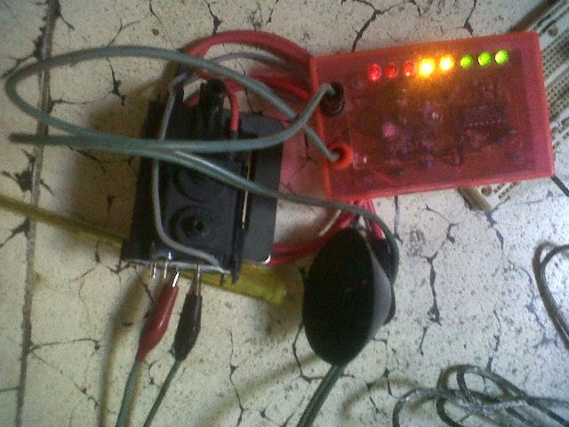
You can see I have tested one flyback which is shorted. The faulty fyback wouldn’t make Ring Tester led lit. It is just one or two led were lit if your flyback faulty, when you have a heavy shorted on your flyback, the led on Ring Tester wouldn’t lit at all. This is my Ring Tester when test a bad flyback.
This below picture when I test good flyback
You can see all led on the Ring Tester is lit. This is a sign for good flyback. Hold on, you must be surprised if you know what else this tester could do. What it is? SMPS Transformer of course!
Did you ever find the faulty SMPS Transformer before? I have found several SMPS Transformer were shorted and I am wondering what if I don’t have this good equipment. Just build or buy it if you have a budget.
You can find information on the internet. It is really worth your time and your money on this equipment. You can test SMPS transformer primaries with this Ring Tester. You would see the difference from good and bad SMPS transformer, you just need a little time to find your transformer was failed.
As professional technician, you have to do troubleshooting job faster. If you could repair one equipment in the shortest time a day, it means you can repair more equipment on a day !
I am not salesman from Anatek Corporation or elsewhere. I just found this tester really do his job well. I remember one day where I don’t have this tester yet. It was really hard to find the causes from dead TV. I am wondering is SMPS section or high voltage section (horizontal section) were defective. I have tested primary and secondary section, but I couldn’t find the culprit. I waste my time almost two hours to find the culprit and that is non profitable for a technician.
Don't forget to see my DIY ESR Meter design too
If you are a technician, don’t miss this Ring Tester on your repair bench. It is rare to find Linear Power Supply on our equipment today because everything was made with SMPS today. SMPS or Switch Mode Power Supply offers an efficiency and more light than Linear Power Supply with the same performance. It is hard to find a big bulky transformer today on our consumer electronic equipments today because everything were dominated by Switch Mode Power Supply.
The disadvantage about power supply which are difficult to troubleshoot because it’s complexity. We need a reliable tool to help us troubleshoot SMPS. You can’t depend on just one test equipment to repair SMPS, that is a hard job. I’ve found this tester really helped me to do a troubleshooting job. I would never do a repair job without this one because it helped me much.
I build this tester based on Blue Ring Tester schematic from Anatek Corporation manual. See below picture.
You can see I have tested one flyback which is shorted. The faulty fyback wouldn’t make Ring Tester led lit. It is just one or two led were lit if your flyback faulty, when you have a heavy shorted on your flyback, the led on Ring Tester wouldn’t lit at all. This is my Ring Tester when test a bad flyback.
This below picture when I test good flyback
You can see all led on the Ring Tester is lit. This is a sign for good flyback. Hold on, you must be surprised if you know what else this tester could do. What it is? SMPS Transformer of course!
Did you ever find the faulty SMPS Transformer before? I have found several SMPS Transformer were shorted and I am wondering what if I don’t have this good equipment. Just build or buy it if you have a budget.
You can find information on the internet. It is really worth your time and your money on this equipment. You can test SMPS transformer primaries with this Ring Tester. You would see the difference from good and bad SMPS transformer, you just need a little time to find your transformer was failed.
As professional technician, you have to do troubleshooting job faster. If you could repair one equipment in the shortest time a day, it means you can repair more equipment on a day !
I am not salesman from Anatek Corporation or elsewhere. I just found this tester really do his job well. I remember one day where I don’t have this tester yet. It was really hard to find the causes from dead TV. I am wondering is SMPS section or high voltage section (horizontal section) were defective. I have tested primary and secondary section, but I couldn’t find the culprit. I waste my time almost two hours to find the culprit and that is non profitable for a technician.
Don't forget to see my DIY ESR Meter design too
This time I want to share my story to make the distinct design of ESR Meter.
ESR Meter using 3 pieces of IC TL082 designed by Allan Wilcox and some components of his supporters. After I made the ESR Meter it is suitable to use in conjunction with the analog meter on my scale 100uA. The appointment of the needle not linear, so that to read the scale of 0.1 up very easily. The label on the box is the label that I took from a website that is on the label Blue ESR Meter made by Bob Parker.
You can see below picture.
Please note, the ESR Meter can be equipped with buzzer sounds to indicate whether the capacitor we test good or not where we can set on how many ohm range buzzer will go off so we don't need to see the panel meters to shorten the time in the repair.
You can see below picture.
Please note, the ESR Meter can be equipped with buzzer sounds to indicate whether the capacitor we test good or not where we can set on how many ohm range buzzer will go off so we don't need to see the panel meters to shorten the time in the repair.
I print the layout with the wrong position so that IC should be installed upside-down, but with a little gently I have successfully completed and are very satisfied with the performance of this ESR Meter. I always fix the TV with the help of ESR Meter. Wanna see my first DIY ESR Meter? Look at this.
This time I want to share my story to make the distinct design of ESR Meter.
ESR Meter using 3 pieces of IC TL082 designed by Allan Wilcox and some components of his supporters. After I made the ESR Meter it is suitable to use in conjunction with the analog meter on my scale 100uA. The appointment of the needle not linear, so that to read the scale of 0.1 up very easily. The label on the box is the label that I took from a website that is on the label Blue ESR Meter made by Bob Parker.
You can see below picture.
Please note, the ESR Meter can be equipped with buzzer sounds to indicate whether the capacitor we test good or not where we can set on how many ohm range buzzer will go off so we don't need to see the panel meters to shorten the time in the repair.
You can see below picture.
Please note, the ESR Meter can be equipped with buzzer sounds to indicate whether the capacitor we test good or not where we can set on how many ohm range buzzer will go off so we don't need to see the panel meters to shorten the time in the repair.
I print the layout with the wrong position so that IC should be installed upside-down, but with a little gently I have successfully completed and are very satisfied with the performance of this ESR Meter. I always fix the TV with the help of ESR Meter. Wanna see my first DIY ESR Meter? Look at this.
ESR Meter is not a new thing. Some are commercial and many DIY projects too on the Internet. I have ever heard my friend said "If electronics equipment still has bad caps, there are still many technicians.
I think ESR Meter really useful when you are troubleshooting some faulty electronic equipment, you can't tell just from capacitor looks good, because capacitor couldn't judge just by capacitance value, they have gone high in their "inner" resistor and make your electronics equipment failed.
As Wikipedia said ESR Meter is
"An ESR meter is a two-terminal electronic measuring instrument designed and used primarily to measure the equivalent series resistance (ESR) of real capacitors; usually without the need to disconnect the capacitor from the circuit it is connected to. Most ESR meters work by applying voltage pulses to the capacitor under test which are too short to appreciably charge it; any voltage appearing across the capacitor is due to ohmic drop across the ESR. Measuring ESR can also be done by applying an alternating voltage at a frequency at which the capacitor's reactance is negligible, in a voltage divider configuration.
Other types of meter, including normal capacitance meters, cannot be used to measure a capacitor's ESR, although a few combined meters are available which measure both ESR and out-of-circuit capacitance. A standard (DC) milliohmmeter cannot be used to measure ESR, because a steady direct current cannot be passed through the capacitor."
ESR or Equivalent Series Resistance of real capacitors. Resistance??
Yup !! capacitor has a resistance, identically ESR like as a resistor that attached or added to capacitor capacitance. Below picture is the analogy example.
I take from a Wikipedia quote :
"Other types of meter, including normal capacitance meters, cannot be used to measure a capacitor's ESR, although a few combined meters are available which measure both ESR and out-of-circuit capacitance. A standard (DC) milliohmmeter cannot be used to measure ESR, because a steady direct current cannot be passed through the capacitor."So it means we as repairer needs this tool after AVO meter or digital meter. I want to share my experience in building this tool. Actually, I get the schematic from another website.
So, I prepare the components to make this ESR Meter from here
Finally, my ESR Meter was done and I can't wait to test it. I found my wall wart adapter power supply has failed because one of capacitor gone high in ESR value, regardless no sign of bulging. I replace the new capacitor and my wall wart adapter brought back to live. I have very happy had these tools on my repair bench because it's very useful. I conclude this ESR Meter really needed by a technician to search for a bad capacitor.
ESR Meter is not a new thing. Some are commercial and many DIY projects too on the Internet. I have ever heard my friend said "If electronics equipment still has bad caps, there are still many technicians.
I think ESR Meter really useful when you are troubleshooting some faulty electronic equipment, you can't tell just from capacitor looks good, because capacitor couldn't judge just by capacitance value, they have gone high in their "inner" resistor and make your electronics equipment failed.
As Wikipedia said ESR Meter is
"An ESR meter is a two-terminal electronic measuring instrument designed and used primarily to measure the equivalent series resistance (ESR) of real capacitors; usually without the need to disconnect the capacitor from the circuit it is connected to. Most ESR meters work by applying voltage pulses to the capacitor under test which are too short to appreciably charge it; any voltage appearing across the capacitor is due to ohmic drop across the ESR. Measuring ESR can also be done by applying an alternating voltage at a frequency at which the capacitor's reactance is negligible, in a voltage divider configuration.
Other types of meter, including normal capacitance meters, cannot be used to measure a capacitor's ESR, although a few combined meters are available which measure both ESR and out-of-circuit capacitance. A standard (DC) milliohmmeter cannot be used to measure ESR, because a steady direct current cannot be passed through the capacitor."
ESR or Equivalent Series Resistance of real capacitors. Resistance??
Yup !! capacitor has a resistance, identically ESR like as a resistor that attached or added to capacitor capacitance. Below picture is the analogy example.
I take from a Wikipedia quote :
"Other types of meter, including normal capacitance meters, cannot be used to measure a capacitor's ESR, although a few combined meters are available which measure both ESR and out-of-circuit capacitance. A standard (DC) milliohmmeter cannot be used to measure ESR, because a steady direct current cannot be passed through the capacitor."So it means we as repairer needs this tool after AVO meter or digital meter. I want to share my experience in building this tool. Actually, I get the schematic from another website.
So, I prepare the components to make this ESR Meter from here
Finally, my ESR Meter was done and I can't wait to test it. I found my wall wart adapter power supply has failed because one of capacitor gone high in ESR value, regardless no sign of bulging. I replace the new capacitor and my wall wart adapter brought back to live. I have very happy had these tools on my repair bench because it's very useful. I conclude this ESR Meter really needed by a technician to search for a bad capacitor.
Subscribe to:
Posts (Atom)